How Pole Height Changes the Whole Performance of a Distribution Line
A practical engineering guide to electric pole height — how it controls wire clearance, sag behavior, wind resistance, foundation stress, and long-term reliability across urban, highway, and industrial site conditions.
Application-specific supply with quality assurance and pan-India dispatch from Vishwageeta Ispat.
Request Quote24-Hour Response Join WhatsApp ChannelDaily Rate Updates Call: 9200049000Direct Sales Line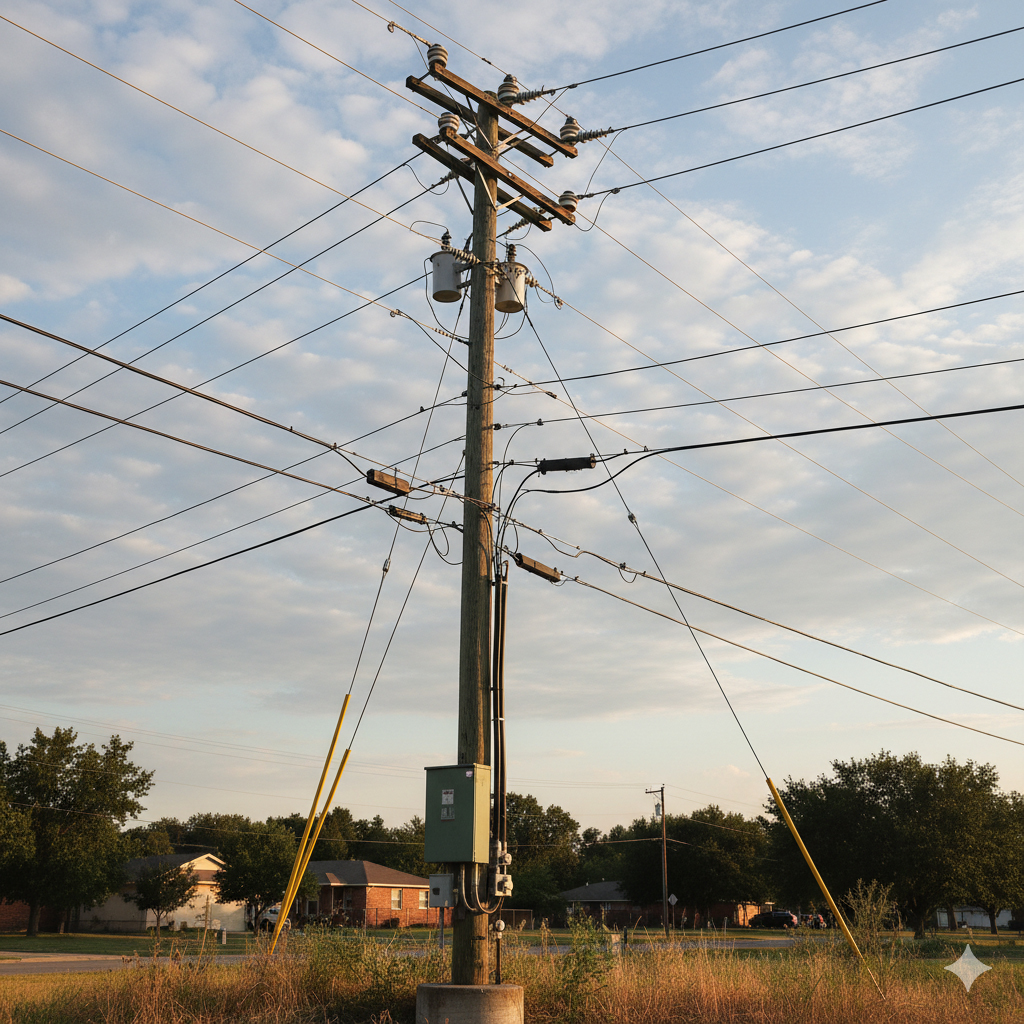
Fig 1 — Correct pole height keeps conductors safe, stable, and service-ready across changing weather, load, and site conditions.
Electric pole height is often treated like a minor measurement — but it directly governs wire clearance, cable sag control, wind resistance, foundation stress, and long-term maintenance burden. Too short, and conductors sag into unsafe zones. Too tall without matching design, and wind stress and tilt risk increase. Correct height is the balance point for safe, stable, service-ready distribution infrastructure.
- Why height matters more than it looks — Clearance, sag, and performance
- Why one height does not work everywhere — Urban, highway, industrial differences
- Safety and stability impact — What actually changes with height
- Engineering logic behind height selection — Inputs, calculation, CEA standards
- Wind load and foundation interaction — How height multiplies structural demand
- Future infrastructure planning — Smart city and multi-utility considerations
- Site verification checklist
- FAQ — Electric pole height questions
Why Electric Pole Height Matters More Than It Looks
Conductor Clearance • Sag Control • Safety Margin • Service Life
Electric pole height is a safety specification first, not a structural aesthetic. It determines the minimum clearance between live conductors and the ground, vehicles, buildings, and people below. This clearance must be maintained under the worst possible condition — peak summer heat when conductors expand, high wind when cables sway, and maximum load when sag is greatest.
Get height right and the network runs quietly for decades. Get it wrong and the consequences compound — more maintenance visits, more sag corrections, more safety incidents, and premature replacement of poles that should have lasted 30–40 years.
CEA (Central Electricity Authority) safety regulations prescribe minimum ground clearances for every voltage level. Pole height is then derived backward from these clearances — adding maximum sag under peak temperature, plus installation tolerance and embedment depth. Selecting height without this calculation creates an unsafe network from day one.
Why One Pole Height Does Not Work Everywhere
Urban Roads • Highways • Industrial Zones • High-Tension Corridors
Many project planners assume a single standard height can be applied across a route. In practice, different site conditions demand different heights because the clearance requirement, traffic profile, and structural loads all change from zone to zone.
Residential & Commercial Lanes
Moderate heights matched to building setbacks, street widths, and existing infrastructure. Maintenance access is frequent and relatively easy. Primary requirement: clearance over pedestrians, two-wheelers, and cars. Typical range: 7–9 m above ground.
National & State Highways
Taller poles required for clearance over heavy vehicles, double-decker transport, and for thermal wire expansion in long spans. Also requires greater sag allowance because span distances are longer. Typical requirement: additional 1–2 m above urban standard.
Factories & Construction Sites
Highest clearance requirements due to crane operation, oversized load vehicles, construction equipment, and material movement above ground level. Strict CEA regulations apply. Poles must clear all equipment at maximum operating reach, not just normal traffic height.
MV & HV Distribution Lines
Stricter overhead safety margins governed by IS standards and CEA voltage-specific clearance requirements. Higher voltage = greater required clearance. Longer spans also allow more sag, requiring additional height to compensate while maintaining minimum clearance at midspan.
Safety and Stability — What Actually Changes With Height
Under-Height Risk • Over-Height Risk • Balanced Design
Height selection is not a one-way optimization — both under-specification and over-specification without matching structural design create distinct problems. Understanding both failure modes helps project teams ask better questions and avoid both extremes.
| Height Condition | Primary Risk | Operational Effect | Likely Outcome |
|---|---|---|---|
| Too Low | Conductor sag reduces clearance in heat — particularly dangerous at midspan | Higher safety incidents, repeated correction work, public hazard risk | Premature replacement or emergency uplift work before designed service life |
| Too High (without matching design) | Wind overturning moment increases with H² — stresses foundation beyond design limit | Progressive tilt, foundation cracking, accelerated fatigue at base | Structural failure or collapse under storm conditions — often without prior visible warning |
| Correct Height + Matched Design | Controlled sag within clearance limits — no safety exceedance under design conditions | Stable service across all seasons, low maintenance frequency, predictable performance | Full 30–50 year service life achieved with routine inspection and minor maintenance only |
Engineering Logic Behind Electric Pole Height Selection
CEA Clearance Standards • Sag Calculation • Site-Specific Inputs
Selecting the right pole height is a combined engineering process — not a rule-of-thumb decision. Engineers work backward from CEA minimum clearance requirements, add maximum sag under design conditions, then determine the minimum above-ground height required. Foundation embedment depth is then added to arrive at total pole length.
Step-by-Step Calculation Logic
Start with the CEA minimum ground clearance for the voltage level and road type. Add the maximum conductor sag expected at peak operating temperature and maximum conductor tension. Add a safety factor for installation tolerances. This gives the minimum height of the conductor attachment point above ground — which determines minimum pole above-ground height. Add foundation embedment (typically 1/6 to 1/5 of total pole length) to get total required pole length.
Key Engineering Inputs
- Span length: longer spans create more sag — requiring greater clearance height to compensate at midspan
- Conductor type and weight: heavier conductors increase tension, sag, and deflection behavior
- Soil condition: weak soil requires deeper embedment — which increases total pole length requirement
- Wind zone class (IS 875 Part 3): higher wind zones require stronger sections and deeper foundations, not necessarily taller poles
- Seasonal temperature range: thermal expansion and contraction determine the sag band width that must be accommodated within the clearance margin
Wind Load and Foundation Interaction
Overturning Moment • Embedment Depth • Section-Height Coordination
One of the most underappreciated consequences of pole height is its effect on wind-induced structural demand. The bending moment at the base of a pole from horizontal wind load does not increase linearly with height — it increases approximately with the square of the effective height. A pole 20% taller than required can experience up to 44% higher wind bending moment at its base.
Why This Matters for Foundation Design
When a project specifies a taller pole to provide extra clearance margin — without recalculating the foundation — the foundation may be dangerously under-designed for the actual structural demand. The pole may stand perfectly for years in normal conditions, then fail suddenly during a severe storm when the actual bending moment exceeds the foundation's resistance capacity.
This is why height, section size, and foundation depth must always be specified and designed together as a system — not as three independent parameters chosen separately.
Foundation Embedment Rules
- Typical embedment ratio: 1/6 to 1/5 of total pole length below ground for standard soil conditions
- Weak soil adjustment: embedment depth increased, sometimes with concrete backfill or stub foundation
- High wind zones: may require bracing, stay wires, or increased section wall thickness rather than deeper embedment alone
- Waterlogging check: monsoon waterlogging can temporarily reduce soil bearing capacity — embedment should account for saturated soil conditions
- Base corrosion protection: the ground-line zone is most vulnerable to steel corrosion — adequate coating and inspection schedule is critical
Future Infrastructure Will Raise Height Planning Complexity
Road Widening • Vertical Urbanization • Smart City Multi-Utility Design
Infrastructure planners increasingly need to consider not just today's clearance and load requirements, but how urban conditions will change over the next 20–30 years. Road widening, vertical construction, heavier traffic profiles, and smart city technology integration are all raising the bar for what a pole must accommodate over its design life.
Changing Urban Conditions
Cities are expanding vertically and roads are widening, often increasing the required clearance height retroactively for existing poles. New construction may reduce setback distances, bringing buildings closer to live conductors. Traffic profiles are changing as heavy goods vehicles become more common in previously light-traffic zones. Projects designed to current minimum heights may need costly upgrades within their design life as these changes occur.
Smart City Multi-Utility Demand
Modern network planning increasingly uses poles as mounting points for smart city hardware — CCTV cameras, communication transceivers, LED streetlights, air quality sensors, and EV charging signage. Each additional attachment adds wind sail area, weight, and a potential mounting height requirement. Future-ready pole designs account for these additions at the specification stage, rather than retrofitting standard poles that were not designed for the combined load.
Practical takeaway: Specify pole height with a margin above the current minimum when project conditions indicate road widening, increased traffic, or smart city development within the planned service life. The incremental cost of correct initial specification is far lower than mid-life replacement or emergency height uplift work.
Site Verification Checklist Before Finalizing Pole Height
Technical Inputs • Safety Standards • Future-Proofing
Technical & Regulatory Inputs
- Voltage class: confirm LV, MV, or HV and corresponding CEA minimum clearance requirement
- Span layout: map pole-to-pole distances and calculate maximum midspan sag at peak temperature
- Conductor type: ACSR, AAC, ABC — each has different sag and tension behavior
- Wind zone class: from IS 875 Part 3 map — determines bending demand on section and foundation
- Soil bearing capacity: site soil test or reference data — determines embedment depth and foundation type
- Seasonal temperature range: impacts conductor thermal expansion and sag band width
Site & Future-Proofing Checks
- Traffic profile: confirm maximum vehicle height on this route — highway, industrial, or crane operation
- Building setbacks: measure proximity of structures that may reduce effective clearance
- Road widening plans: check municipal or highway authority records for planned widening within 10 years
- Future load additions: account for planned telecom cable, streetlighting, or smart city hardware mounting
- Monsoon waterlogging: assess risk of seasonal soil weakening around foundation zone
- Qualified engineering sign-off: final height specification must be validated by a qualified structural or electrical engineer
• Central Electricity Authority (CEA) — Safety regulations for ground clearance and line design
• Bureau of Indian Standards (BIS) — IS 875 Part 3 wind load maps; IS 1863, IS 7321 pole specifications
• Ministry of Power, Government of India — Distribution network guidelines and standards reference
FAQ — Electric Pole Height Questions Answered
Safety Standards • Calculation Methods • Site-Specific Guidance
Vishwageeta Ispat — Raipur, Chhattisgarh
Vishwageeta Ispat supplies electric poles, RSJ sections, and structural steel for utility, distribution, and industrial infrastructure across Chhattisgarh and Central India. Our poles are supplied to IS standards with full documentation. We provide transparent landed-cost quotations for projects of any scale — with pan-India dispatch and same-day commercial response.
Need application-specific supply guidance or a quote for your utility pole project? Contact our team today — we respond within 24 hours with confirmed pricing and availability.